If your MIG welder keeps popping, burning through, or throwing spatter everywhere, your wire speed and voltage are not working together.
Wire speed controls how fast filler metal feeds into the joint. Voltage controls arc length and bead shape. When those two settings match, the arc sounds smooth, and the weld looks clean.
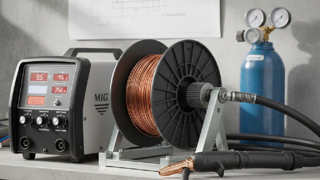
This MIG welding wire speed and voltage chart gives you clear starting points based on wire size and metal thickness. You can also treat it as a quick guide for MIG welding wire speed and voltage settings when you’re dialing in a new job.
What Is the MIG Welding Wire Speed and Voltage Chart?
A MIG welding wire speed and voltage chart gives you recommended voltage (V) and wire feed speed (IPM) based on wire diameter and material thickness.
Think of it as your baseline. It won’t replace real testing, but it saves you from guessing and wasting wire. Start with these values, then adjust for joint type, shielding gas, and welding position.
0.023″ (0.6 mm) Wire Settings
Best for thin sheet metal and light fabrication work.
| Material Thickness | Voltage (V) | Wire Speed (IPM) |
| 1 mm | 14–15 | 90–140 |
| 2 mm | 15–16 | 120–180 |
| 3 mm | 16–17 | 150–220 |
| 4 mm | 17–18 | 180–260 |
This size reduces burn-through risk and gives better control over thin steel.
0.030″ (0.8 mm) Wire Settings
Most common wire size for general fabrication.
| Material Thickness | Voltage (V) | Wire Speed (IPM) |
| 2 mm | 16–17 | 140–200 |
| 3 mm | 17–18 | 180–260 |
| 4 mm | 18–19 | 220–300 |
| 5 mm | 19–21 | 260–340 |
This wire balances penetration and control for most shop work.
0.035″ (0.9 mm) Wire Settings
Best for thicker steel and structural welding.
| Material Thickness | Voltage (V) | Wire Speed (IPM) |
| 3 mm | 18–19 | 200–280 |
| 4 mm | 19–21 | 240–320 |
| 6 mm | 21–23 | 280–360 |
| 8 mm | 23–25 | 320–400 |
This size produces deeper penetration and stronger weld joints.
How Should You Use the MIG Welding Chart Correctly?
Use the chart as your starting point, then adjust based on real welding conditions.
Charts assume flat-position welding with standard shielding gas. But real projects rarely stay perfect. Joint gaps vary. Metal temperature changes. Even your machine’s power delivery can shift slightly.
Here’s how to adjust safely:
- Change Voltage in 0.5–1 Volt Steps: Small changes prevent overheating or undercut.
- Adjust Wire Speed In 10–20 IPM Increments: Large jumps usually cause instability.
- Test On Scrap First: Always verify penetration before welding final parts.
Small adjustments give you control. Big adjustments usually create new problems.
Why Must Wire Speed and Voltage Match?
Wire speed and voltage must increase or decrease together to maintain arc stability and proper penetration.
If the wire speed is too high and the voltage is too low, the wire physically pushes into the puddle. You’ll hear harsh popping and see heavy spatter.
If the voltage is too high and the wire speed is too low, the arc stretches too long. The bead flattens, and an undercut may form along the edges.
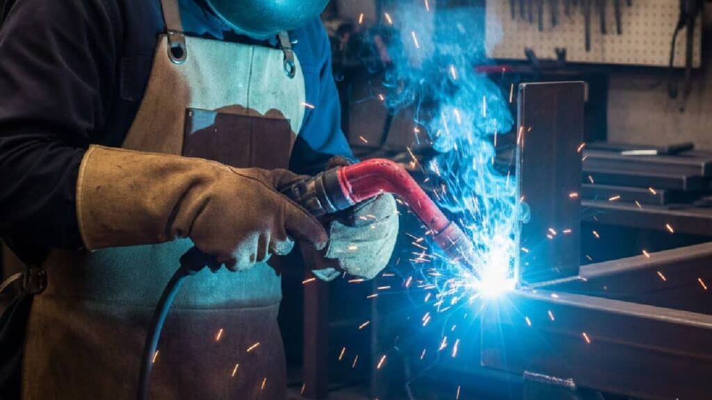
Balanced settings feel different. You’ll hear a steady “frying bacon” sound. The puddle flows smoothly. Spatter stays minimal. Once you hear that sound, you’ll know you’re close.
(If it sounds like popcorn in a microwave, something’s off.)
What Happens If Wire Speed Is Too High?
When the wire speed is too high, the wire hits the puddle before it has time to melt. That’s why the arc feels “pushy” and loud.
You’ll usually notice:
- The Arc Stubs Into The Pool
- Harsh Popping Sounds
- Heavy Spatter Around The Joint
In most cases, the voltage is too low for the selected feed speed. Increase the voltage slightly to restore balance.
What Happens If Voltage Is Too High?
When the voltage is too high, the arc stretches too long and loses focus.
You may see:
- A Long, Wandering Arc
- A Flat, Wide Bead
- Undercut Along The Edges
Lower the voltage slightly until the puddle tightens and becomes more controllable.
What Balanced Settings Look and Sound Like?
Correct settings produce:
- Steady “frying bacon” sound
- Smooth, even bead profile
- Minimal spatter
- Proper penetration without burn-through
If the arc sounds harsh or popping, something is off.
How Do You Set MIG Wire Speed and Voltage Step by Step?

Follow this 5-step method for consistent results:
Step 1: Choose The Correct Wire Size
Select a wire based on material thickness.
- Use 0.023″ for thin sheet metal.
- Use 0.030″ for general fabrication.
- Use 0.035″ for 6 mm steel and thicker.
Step 2: Set Voltage First
Dial in the voltage based on the chart. Voltage determines arc length and bead profile.
Step 3: Increase Wire Feed Gradually
Raise the wire speed slowly until the arc stabilizes. Stop when the sound becomes steady and smooth.
Step 4: Run A Test Weld
Always weld on a scrap of the same thickness. Check penetration and bead shape.
Step 5: Fine-Tune In Small Increments
Make small changes only. Large changes usually overshoot the correct range.
What MIG Settings Should You Use for Different Materials?
Different metals react differently to heat, so settings vary.
Mild Steel
Mild steel follows standard chart values.
Use 75/25 Argon-CO₂ for smooth arc performance.
Stainless Steel
Stainless requires slightly lower wire speed to control heat input.
Use higher argon blends for better stability.
Aluminum
Aluminum requires:
- Higher wire speed
- Pure argon shielding gas
- Smooth wire feeding system
Aluminum melts faster, so precise control is critical.
How Does Shielding Gas Affect Voltage and Wire Speed?
Different shielding gases change how your arc behaves.
100% CO₂ runs hotter and feels more aggressive. It delivers deeper penetration but produces more spatter. You’ll often need slightly higher voltage to stabilize the arc. Fabricators commonly use it for thick structural steel where strength matters more than appearance.
75/25 Argon-CO₂ gives you a smoother arc and cleaner bead. That’s why most shops use it for mild steel. It balances penetration and control without excessive cleanup.
90/10 Argon blends create a softer, more stable arc with lower heat input. They’re well-suited for thin materials and stainless steel.
If you switch gases, don’t expect your old settings to behave the same. Adjust the voltage slightly and re-test.
How Can You Tell If Your MIG Settings Are Correct?
Correct MIG settings produce clean visual and audible indicators.
Look for:
- Steady Arc Sound
- Flat, Uniform Bead
- Minimal Spatter
- Consistent Wire Feed
- Proper Penetration Without Burn-Through
If penetration is weak, increase both voltage and wire speed slightly.
Quick Fix Cheat Sheet (Fast Troubleshooting)
If you want a faster way to dial in your settings, use this quick checklist:
- Popping + Spatter: Voltage too low for your wire speed → Raise voltage slightly
- Wire Stubbing: Wire speed too high for your voltage → Raise voltage or lower feed speed
- Flat, Wide Bead: Voltage too high → Lower voltage slightly
- Ropey Bead: Voltage too low → Raise voltage slightly
- Weak Penetration: Heat input too low → Increase voltage and wire speed together
What Are the Most Common MIG Welding Problems and Fixes?
Most MIG issues come down to heat balance. Here’s how to identify and fix them:
- Excessive Spatter: Low voltage or excessive wire speed causes unstable transfer. Raise the voltage slightly or reduce the feed speed.
- Burn-Through: Too much heat for thin metal. Lower voltage and reduce wire speed together.
- Poor Penetration: Heat input is too low. Increase both voltage and wire speed gradually.
- Wire Stubbing: Wire feed is too fast for the selected voltage. Increase the voltage slightly.
- Tall, Ropey Bead: Voltage is too low. Raise the voltage to flatten the bead and improve fusion.
What Advanced Factors Affect MIG Wire Speed and Voltage?
Even perfect chart settings can change once you’re welding in the real world. Here are the three variables that throw settings off the fastest.
Stick-Out Length
Electrode stick-out directly affects heat input. A longer extension reduces current and penetration. Keep it between 3/8″ and 1/2″ for stable transfer. If penetration suddenly drops, check your stick-out first.
Welding Position
Vertical and overhead welding require lower heat input to prevent the puddle from sagging. Reduce voltage and wire speed slightly when welding out of position.
Machine Type
Inverter welders offer finer voltage control than transformer machines. Two machines set at 18 volts may not behave the same. Always test on scrap when switching equipment.
Conclusion
Balancing wire speed and voltage is the foundation of strong MIG welding.
Start with the chart. Test on scrap. Adjust in small increments. Listen to the arc and watch the puddle. When the sound smooths out and the bead flows evenly, you’re in the right range.
Over time, you won’t rely on charts as much. You’ll rely on feel and sound.
If you’re setting up a new machine or upgrading your welding equipment, choose gear that gives you stable voltage control and consistent wire feeding. That stability makes tuning faster and welding cleaner.
FAQs About MIG Wire Speed and Voltage
The correct voltage and wire speed depend on wire diameter and metal thickness. For example, 0.030″ wire on 4 mm steel typically uses 18–19 volts and 220–300 IPM. Always start with a welding chart and fine-tune based on arc sound and bead appearance.
Yes. In MIG welding, wire feed speed directly controls amperage. Increasing wire speed increases current, while lowering it reduces amperage. Voltage remains separate and controls arc length.
Too much voltage creates a long, unstable arc and a flat, wide weld bead. It may cause undercut and excessive heat input. Lower the voltage slightly if the arc sounds harsh or the bead spreads too wide.
0.8 mm wire works better for medium-thickness steel and general fabrication. 0.9 mm wire provides deeper penetration and suits thicker material, but requires higher voltage and wire speed.
To reduce spatter, balance voltage and wire speed, use 75/25 shielding gas, maintain proper stick-out, and clean the base metal. Most spatter results from incorrect parameter balance.