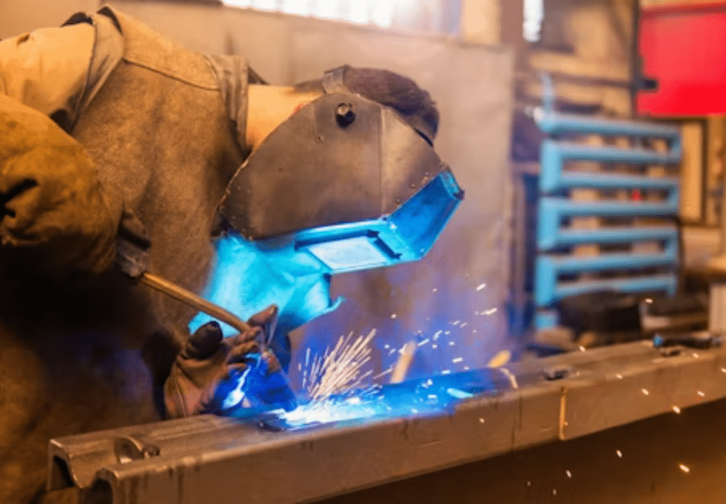
Welding heat-resistant alloys is harder than welding standard steel because small mistakes can turn into early service failures. If the joint is dirty, the filler is wrong, or heat control slips, a weld that looks acceptable at first may not last long in high-temperature service.
In this guide, we’ll show you where these welds usually fail, how the risks change by alloy family, and what you should check before, during, and after welding.
Why Are Heat-Resistant Alloys Harder to Weld Than Standard Steels?
Heat-resistant alloys are harder to weld because they leave less room for error under long-term heat. Standard steel often gives you some margin. These alloys usually do not.
High-Temperature Service Leaves Less Room for Defects
Heat-resistant parts often run for long periods in furnace tubes, exhaust systems, reformer parts, and hot piping. In that kind of service, even small weld flaws become more serious.
These alloys are less forgiving for three main reasons:
- Creep Can Grow Small Flaws Over Time: Long exposure to heat and load can turn a minor defect into a larger crack.
- Thermal Cycling Adds Stress To The Joint: Repeated heating and cooling can open weak areas that looked harmless at first.
- Oxidation Speeds Up Damage in Weak Zones: Once the weld area is compromised, oxidation can push the failure faster.
A lack of fusion that might stay hidden in mild steel for years can become a real service problem much sooner in a hot-service alloy.
Oxide Scale and Contamination Block Fusion
Dirty surfaces cause more trouble on heat-resistant alloys because contamination can block fusion and contaminate the weld pool early. Even small amounts of shop dirt can ruin a root pass.
Before welding, watch for:
- Oxide Scale
- Oil And Grease
- Sulfur-Bearing Residue
- Marker Ink And Shop Dirt
If the root pass starts on a dirty joint, the rest of the weld usually does not get better from there.
Thermal Expansion and Solidification Raise Cracking Risk
Some heat-resistant alloys crack more easily because the weld expands, shrinks, and solidifies under higher stress. Nickel alloys are a common example.
Cracking risk rises when you have:
- High Joint Restraint
- Poor Fit-Up
- Narrow, Deep Beads
- Too Much Heat In One Area
That is one reason bead shape and fit-up matter so much on these jobs.
HAZ Changes Can Reduce Long-Term Stability
The HAZ can lose part of the structure that gives the base metal its long-term service strength. On creep-resistant ferritic steels, that weak zone may form beside the weld and crack later in service.
That is why you need tighter control over:
- Preheat
- Interpass Temperature
- PWHT
- Procedure Limits For The Specific Grade
If you are welding hot-service ferritic steel, the job does not end when the bead looks good. The later heat history still matters.
How Do Nickel-Based Alloys and High-Cr Ferritic Steels Create Different Welding Risks?

Nickel-based alloys and high-Cr ferritic steels do not fail in the same way, so you should not weld them with the same mindset. Both are used in high-temperature service, but their welding risks start in different places.
Nickel-Based Alloys Tend to Show Hot Cracking and Sluggish Weld Pools
Nickel-based alloys are more prone to hot cracking, and the weld pool often feels slower and heavier. That can push welders into bad habits if they are not careful.
Common trouble points include:
- Pausing Too Long
- Widening The Bead Too Much
- Letting Contamination Ride Into The Pool
- Losing Bead Consistency
On thin sections or root work, TIG often gives better puddle control.
High-Cr Ferritic Steels Are More Sensitive to HAZ Hardening and Delayed Cracking
High-Cr ferritic steels are more sensitive to hard HAZ formation and delayed cracking after welding. This can fool you because the weld may look acceptable at first.
Risk goes up when these three conditions stack together:
- Hydrogen Is Present
- Cooling Happens Too Fast
- The Joint Has High Restraint
That is why some ferritic welds need hold time and later reinspection instead of a quick visual check and a thumbs-up.
Filler Metal Rules Are Not the Same for Both Alloy Families
Filler selection should follow the alloy family, service condition, and qualified procedure, not shop habit. A filler that works on one alloy family can create long-term trouble on another.
A simple way to think about it:
- Nickel-Based Alloys: Filler often needs to support chemistry match and crack resistance.
- High-Cr Ferritic Steels: Filler often needs to support strength, heat treatment response, and service life.
- Both Families: The WPS and base metal grade should decide the filler, not whatever rod is closest to your bench.
That sounds obvious, but filler mix-ups still happen more often than they should.
Base Metal Condition and Prior Service Exposure Can Raise Weld Risk
Used hot-service parts can carry damage that changes how the weld behaves. If you are repairing an older header, manifold, or furnace tube, do not treat it like clean new stock.
Check for conditions such as:
- Scale Build-Up
- Carburization
- Decarburization
- Creep Damage
- Old Repair History
When you are working on repair welds, the metal’s past life matters. Sometimes it matters a lot.
What Should You Check Before Welding Heat-Resistant Alloys?
Check cleanliness, tooling, fit-up, consumables, and WPS limits before welding heat-resistant alloys. Most avoidable problems start before arc time, which is why good pre-weld discipline pays off fast.
Remove Oxides, Grease, Sulfur, and Shop Contamination
Clean the joint and filler before welding because contamination is one of the fastest ways to ruin weld quality. Do not expect the arc to burn through it.
Before welding, remove:
- Oxide Scale
- Grease And Oil
- Paint And Moisture
- Sulfur-Bearing Residue
- Dirty Marker Lines
- Loose Shop Dirt
Clean both the joint faces and the filler wire. Start with a suitable solvent, then use the right mechanical cleaning method for the alloy.
Use Dedicated Tools to Avoid Cross-Contamination
Use dedicated brushes, discs, and work surfaces to keep contamination out of the weld. Shared tools are a common shortcut, and they cause real trouble in alloy work.
Your alloy prep tools should include:
- Dedicated Stainless Or Alloy Brushes
- Clean Grinding Discs
- Separate Work Surfaces
- Clearly Tagged Tools For Alloy Use Only
A carbon steel brush used on a nickel alloy repair can drag contamination right where you do not want it.
Review Joint Design, Fit-Up, and Restraint Before Welding
Check the joint geometry before welding because poor fit-up raises cracking risk and makes fusion harder to control. This matters even more on thick or restrained parts.
Review items such as:
- Joint Angle
- Root Opening
- Land
- Backing Plan
- Tack Quality
- Clamp Setup
- Overall Restraint Level
If the groove shape forces you into a hot, wide weave just to reach the sidewall, the setup needs work before welding starts.
Confirm Filler, Shielding, and WPS Limits Before You Start
Confirm the filler, shielding plan, and procedure limits before you strike an arc. A quick check at the bench is cheaper than a failed repair or an unplanned shutdown.
Verify these items first:
- Filler Classification
- Filler Lot Condition
- Shielding Gas
- Purge Plan
- Preheat Range
- Interpass Limit
- PWHT Requirement
This is the step many shops rush. It is also the step that prevents a lot of rework.
What Process Controls Matter Most During Welding?
Watch heat input, interpass temperature, penetration, dilution, bead shape, shielding coverage, and travel speed during welding. These controls decide whether the weld looks sound now and still survives later heat exposure.
If you lose control of even one or two of them, you can end up with the worst kind of repair: a weld that looks decent on the surface and still fails underneath.
i)Keep Heat Input and Interpass Temperature Inside the Qualified Range
Heat control affects both fusion and long-term stability. Too much heat can widen weak zones in the HAZ. Too little heat can cause a lack of fusion.
During welding, pay attention to three basics:
- Measure Actual Interpass Temperature: Do not rely only on the planned number, especially on thick or highly restrained joints.
- Avoid Heat Build-Up Over Multiple Passes: The workpiece can hold more heat than expected as the weld progresses.
- Stay Inside the WPS Range: This is one place where “close enough” usually is not close enough.
ii)Control Penetration, Dilution, and Bead Shape Through Setup
Your setup should give you sound fusion without creating an unstable bead profile. On heat-resistant alloys, narrow deep beads and excess dilution create trouble faster than many welders expect.
Set up the weld to avoid:
- Narrow, Deep Beads
- Poor Sidewall Fusion
- Excess Dilution
If the bead profile already looks wrong in the first passes, do not assume it will fix itself later. It usually will not.
iii)Maintain Stable Shielding Coverage During the Root and Hot Pass
Stable shielding keeps air and contamination out of the weld pool. This matters even more on root passes, hot passes, and oxidation-sensitive alloys.
Pay close attention to:
- Gas Flow Stability
- Torch Angle
- Cup Position
- Drafts Around the Joint
- Root Purge Quality Where Required
A weak shielding setup can undo otherwise good welding technique very quickly.
iv)Adjust Travel Speed and Deposition Strategy on Thick or Restrained Joints
Travel speed affects both heat build-up and fusion quality. Move too slowly and you overheat the joint. Move too fast and you can miss sidewall fusion.
For thick or highly restrained joints, use a plan instead of improvising:
- Use a Bead Sequence That Controls Heat Build-Up
- Avoid Random Fill Patterns
- Watch How the Joint Responds After Each Pass
When the groove is deep and restraint is high, “just keep filling it” is not a real strategy.
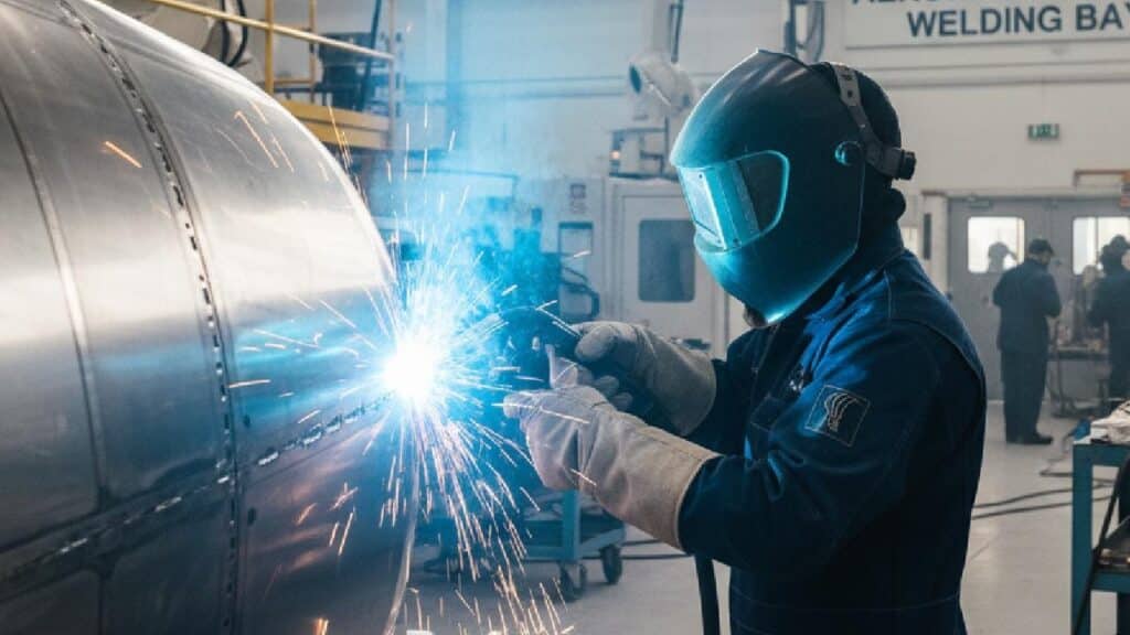
Which Welding Processes, Shielding Methods, and Consumables Work Best?
Choose the welding process and consumables based on section thickness, joint access, alloy family, and service temperature. In many cases, TIG gives you the best control on roots and thin sections, while higher-deposition processes make more sense on fill passes or larger weldments.
- GTAW Gives the Best Control on Thin Sections and Root Passes: TIG offers a stable arc and close puddle control, which helps on thin-wall tubing, open roots, and repair starts. That makes it a strong choice for nickel alloy roots and precision work.
- GMAW or SMAW Can Raise Productivity but Needs Tighter Procedure Control: MIG and stick can speed up fill passes, field repairs, and larger fabrications, but they need sound gas coverage, correct consumables, and close parameter control. YesWelder positions both TIG and MIG equipment for bulk buyers and shop use, which fits jobs that need both root control and fill efficiency.
- Filler Metal Choice Should Follow Service Temperature and Chemistry Match: Match the filler to the alloy family, service condition, and required weld properties. Do not choose filler only by what is already in the cabinet.
- Some Joints Need Root Purge, Backing Gas, or Trailing Shields: Open-root pipe, thin-wall tube, and oxidation-sensitive joints may need purge gas or added shielding behind the weld. Plan the purge before fit-up, not after the root is halfway done.
When Are Preheat, PWHT, and Other Heat Treatments Actually Required?
Preheat and PWHT are required when the alloy grade, thickness, restraint level, or code says they are required. In ferritic creep-resistant steels, they are often a central part of weld quality. On nickel-based alloys, the wrong heat treatment can do more harm than good.
- Preheat Mainly Helps Hardenable Ferritic and Creep-Resistant Steels: Preheat slows cooling and lowers hydrogen-cracking risk in susceptible ferritic steels. It is far less important for many nickel alloys.
- PWHT Should Follow Material Grade, Thickness, and Code Requirements: PWHT can temper hard zones and improve service performance in ferritic steels when the procedure calls for it. Use the qualified range only.
- The Wrong Heat Treatment Can Reduce Properties or Create New Cracks: TWI’s work on Type IV cracking notes that poor heat treatment can contribute to later failures in ferritic weldments.
- Qualified Time-and-Temperature Windows Beat Shop Rules of Thumb: “We always do it this way” is not a procedure. Use the WPS, PQR, material grade data, and code limits.
What Failures Can Show Up After Welding and Later in Service?
The failures that can show up after welding include cold cracking, reheat cracking, Type IV damage, lack of fusion, and oxide-related defects. Some appear in hours. Others take years under hot service.
Cold Cracking in the HAZ
Cold cracking in the HAZ is tied to hydrogen, hard microstructures, and restraint. Reinspect susceptible ferritic welds after a hold period when the procedure requires it. That extra check catches cracks that were not visible right after welding.
Reheat Cracking During PWHT or Repair
Reheat cracking can show up during PWHT or later repair heating. This is one reason repair welds on older hot-service parts deserve close review before you put heat back in.
Type IV Damage in Creep-Resistant Ferritic Steels
Type IV damage forms in the HAZ of creep-resistant ferritic steel weldments during long hot service. TWI describes it as creep cracking at the parent metal and HAZ interface, often in the fine-grained or intercritical HAZ.
Lack of Fusion, Oxide Entrapment, and Their Service Consequences
Lack of fusion and oxide entrapment lowers the effective load path of the joint. In hot service, those defects can become crack starters under thermal stress and creep.
Use this field risk table for Welding Heat-Resistant Alloys before repair work
| Use low-hydrogen practice, apply preheat where required, and reinspect later | What Usually Causes It | What to Do |
| Hot Cracking | Dirty joint, poor bead shape, high restraint | Improve cleaning, control bead profile, reduce restraint |
| HAZ Cold Cracking | Hydrogen, hard HAZ, fast cooling | Use low-hydrogen practice, apply preheat where required, reinspect later |
| Oxide Entrapment | Poor prep, bad shielding, dirty filler | Clean base metal and filler, protect the weld pool well |
| Type IV Damage | Weak HAZ in ferritic creep-resistant steel | Follow qualified heat treatment and service-grade procedure |
| Lack of Fusion | Low heat, bad angle, fast travel | Adjust parameters, torch angle, and joint prep |
How Do You Inspect and Improve Weld Reliability in Real Applications?
You inspect and improve weld reliability by combining visual checks, delayed reinspection where needed, the right NDT method, and better joint design. Inspection is not one step. It is a chain.
Visual Inspection Is Only the First Screen
Visual inspection catches bead shape problems, undercut, overlap, arc strikes, and visible oxidation. It does not prove sound fusion inside the joint.
Reinspect Delayed-Cracking-Sensitive Welds
Reinspect delayed-cracking-sensitive ferritic welds after the hold time required by your procedure or customer standard. This matters on thick sections, hardenable steels, and restrained repairs.
Match the NDT Method to the Alloy Family and Expected Defect Type
Match the NDT method to the likely defect. Surface-breaking cracks may need PT or MT where permitted. Internal flaws may need RT or UT. Porosity and oxide-related defects often show up well on radiography, as ESAB notes in its guidance on weld porosity evaluation.
Reduce Restraint, Notches, and Stress Concentration Where You Can
Reduce restraint, sharp transitions, poor repair geometry, and stress raisers wherever you can. A small grind blend at a weld toe may help more than one extra repair pass.
Conclusion
Welding heat-resistant alloys comes down to disciplined control at every stage: clean prep, the right filler, stable shielding, sound fit-up, and qualified heat treatment where required. These welds are less forgiving than standard steel, so small shortcuts can turn into early service failures.
In practice, the best results usually come from matching the process to the job. TIG makes sense when you need better root control, cleaner starts, or more precision on thin sections. Higher-deposition processes make more sense when the procedure supports them and productivity matters on larger weldments.
If your shop handles alloy work regularly, it is worth reviewing whether your current welding setup matches the jobs you take on most often. A reliable welding equipment supplier can help you compare the right TIG welder or MIG welder for repair work, fabrication, and bulk shop use.
FAQs
No. Shared brushes, discs, and work surfaces can transfer contamination into the joint. For heat-resistant alloy work, use dedicated prep tools and clearly separate them from carbon steel tools.
No. TIG usually gives the best control on root passes, thin sections, and precision repair work, but it is not always the best choice for every weld. MIG or stick can make more sense on fill passes, field repairs, or larger weldments when the procedure supports them.
You usually need a root purge, backing gas, or added shielding on open-root pipe, thin-wall tube, and oxidation-sensitive joints. The best time to plan that setup is before fit-up, not after the root pass has already started.
Not all of them, but many delayed-cracking-sensitive ferritic welds do. Thick sections, high restraint, and hardenable materials often need a hold time and later reinspection when the procedure or customer standard calls for it.
Stop and review the repair when the part shows prior service damage, heavy scale, carburization, decarburization, creep damage, or repeated repair history. Older hot-service parts can behave very differently from new stock, so a quick patch is not always the safe choice.