Railway welding technology is not simply about joining two pieces of rail steel. It is about building continuous track that stays safe, smooth, and structurally reliable under repeated wheel loading, temperature cycles, and decades of service. Get the welding wrong and the consequences show up gradually, as fatigue cracks, rough ride quality, or sudden failures that shut down a line.
This guide covers the main rail welding methods, how to choose between them, why continuous welded rail creates thermal stress challenges, why turnout repair follows different rules, how weld quality is verified, which standards apply, and where the industry is heading next.
Why Is Railway Welding So Important to Track Performance?
Rail joints are the weakest point in any track system. Every time a wheel passes over a gap or a mechanical joint, it delivers an impact load that is significantly higher than the static load of the train above it. Multiply that impact by thousands of wheel passages per day on a busy corridor, and the cumulative fatigue damage at unmanaged joints becomes a serious structural problem.
Rail Joints as Critical Stress Points
Railway welding technology matters because it reduces weak points in the track, improves ride quality, and lowers long-term maintenance work.
Every rail joint creates a small interruption in load transfer. When a wheel passes over that point, the rail end can move slightly. One wheel pass may not sound like much. But on a busy line, that same joint may take thousands of hits every day.
Rail Joints Create Stress Points
Poor joints and weak welds usually cause problems in 3 places:
- At the Rail End: Repeated wheel impact can batter the rail end and create uneven contact.
- Around Bolt Holes: Bolted joints concentrate stress around the holes, which can lead to cracking.
- Under the Sleeper Area: Repeated movement can disturb ballast and create pumping under the track.
Welding helps because it gives the wheel a smoother path. It does not remove every stress problem, but it spreads the load more evenly along the rail.
Better Welding Improves Safety, Ride Quality, and Maintenance
Good rail welding gives track teams 3 practical benefits:
- Better Safety: Fewer joint gaps mean fewer places where fatigue cracks can start.
- Smoother Ride Quality: Continuous rail helps trains run with less vibration, especially at higher speeds.
- Lower Maintenance Work: Welded rail reduces the need for repeated joint inspection, fishplate repair, and ballast correction.
Which Railway Welding Methods Are Used Most Often?
The 4 common railway welding methods are thermite welding, flash-butt welding, gas pressure welding, and electric arc repair welding. Each one fits a different job site, budget, and quality target.
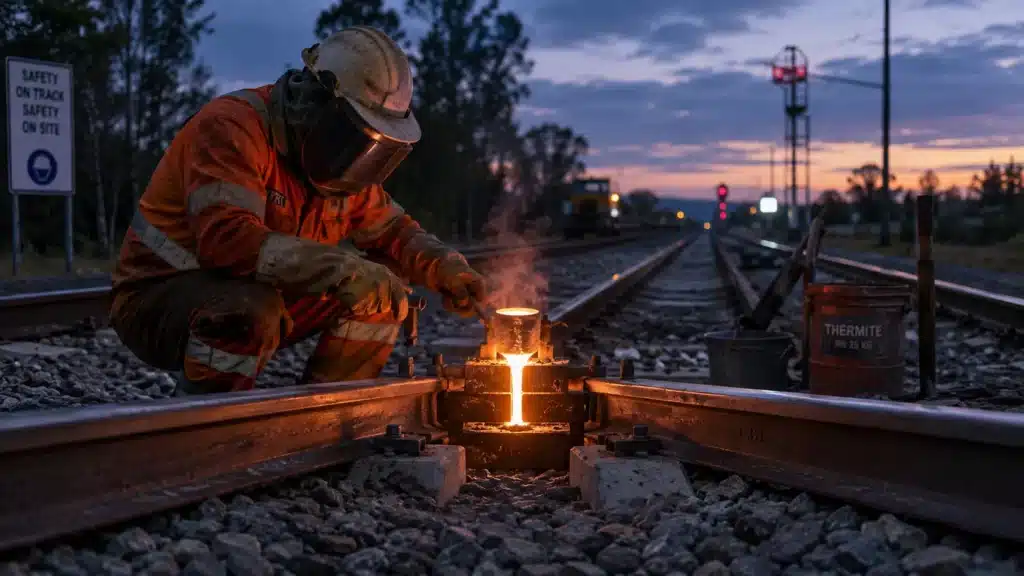
Thermite Welding
Thermite welding is often used for field repair and remote rail work because it does not need a large power source.
It works by using a chemical reaction to create molten steel. That molten steel flows into a mold around the rail ends and forms the weld after cooling.
Thermite welding works well when you need:
- Portable Field Repair: Crews can carry the equipment to remote track locations.
- Lower Equipment Demand: The process does not require a fixed welding plant.
- Flexible Maintenance Work: It is useful for repair jobs where mobile flash-butt equipment cannot reach.
The tradeoff is consistency. Thermite weld quality depends heavily on mold setup, preheating, rail-end preparation, and operator skill.
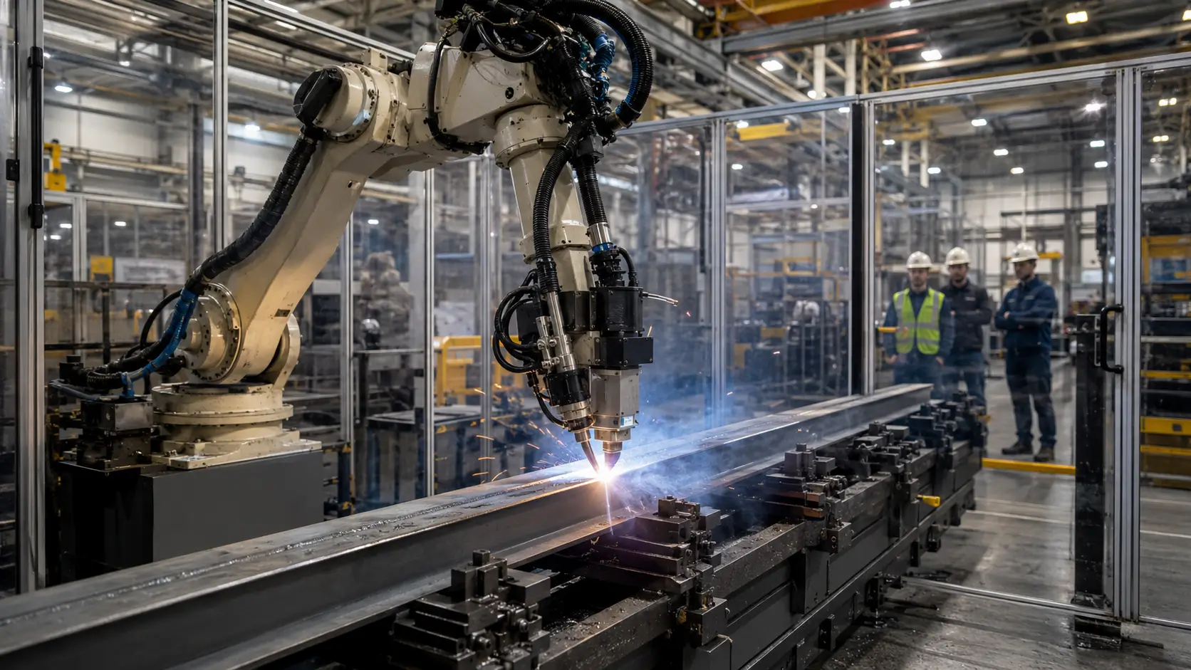
Flash-Butt Welding
Flash-butt welding is often the better choice for high-speed rail, heavy-haul lines, and production welding.
This process uses electrical resistance and pressure to join two rail ends. Once the rail ends reach the right temperature, the machine pushes them together and removes excess heated material from the joint.
Flash-butt welding is strong because it offers:
- Better Process Control: Machines can control current, pressure, and timing.
- Fewer Internal Defects: The process usually produces cleaner welds than field thermite welding.
- Better Geometry Control: This matters when line speed and ride quality are strict.
The limit is access. You need a fixed plant or a mobile flash-butt welding machine, so it is not the easiest option for one-off repairs.
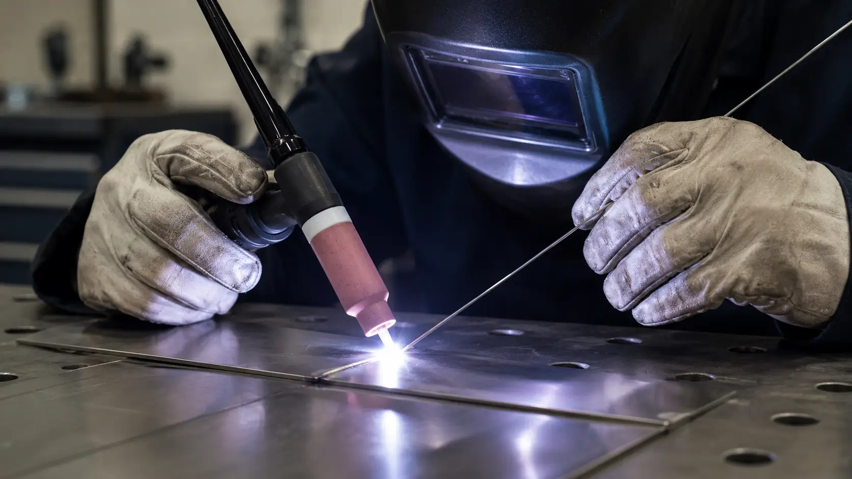
Gas Pressure Welding
Gas pressure welding uses flame heating and axial pressure to join rail ends without filler metal.
You may see this method more often in parts of Asia than in North America or Europe. It can be a practical option for certain mainline rail jobs, but it depends on local standards, crew experience, and available equipment.
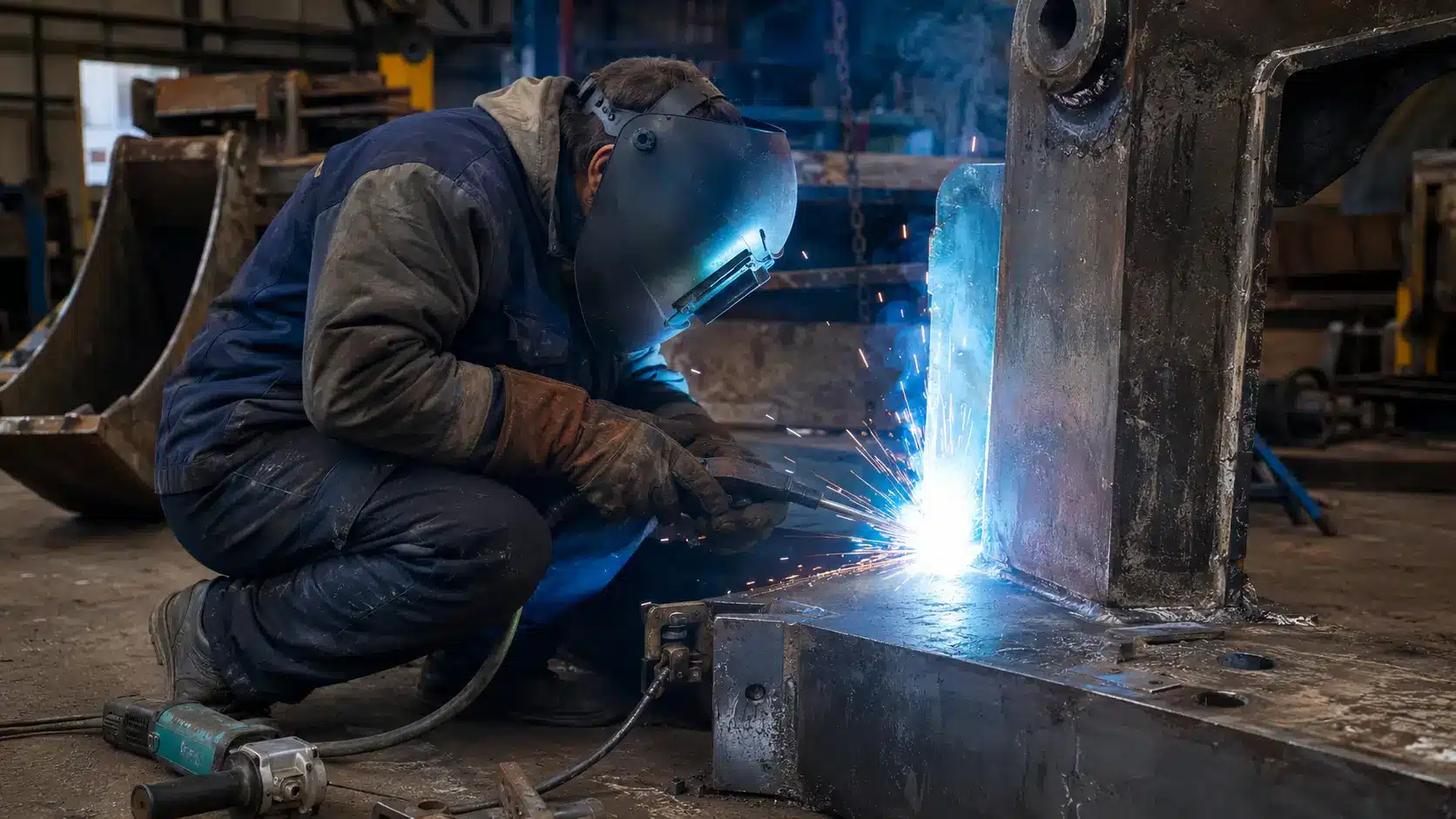
Electric Arc Welding in Localized Rail Repair
Electric arc welding is not usually used as a primary rail joining method, but it still has a clear role in localized rail repair. Crews may use a stick welder with the right electrodes, or a semi-automatic wire process, to build up damaged rail ends, surface defects, and worn areas before grinding them back to profile.
For high-carbon rail steel, electrode choice matters. Low-hydrogen electrodes help reduce the risk of hydrogen-induced cracking, especially when the repair area faces repeated wheel loading after it returns to service.
Rail Welding Process Comparison
| Method | Best Use Case | Main Strengths | Main Limitations |
| Thermite | Remote field repair, secondary lines | Portable, no power required | Operator-dependent quality, porosity risk |
| Flash-butt | High-speed rail, heavy haul, production welding | Consistent quality, strong mechanical properties | Requires specialist equipment or plant |
| Gas pressure | Regional mainline welding (Asia-Pacific) | No filler, good fusion | Less common in Western practice |
| Electric arc | Localized surface repair, turnout buildup | Flexible, accessible equipment | Not suitable for primary rail joining |
What Equipment Do You Need for Railway Welding?
Railway welding needs more than a heat source. You also need the right alignment tools, power setup, grinding equipment, and inspection records to make the weld repeatable.
Mobile Welding Units and Power Systems
Flash-butt welding needs heavier equipment than thermite welding.
For field flash-butt welding, crews usually rely on mobile welding machines mounted on rail vehicles. These units carry the transformer, clamps, control system, and pressure equipment needed to complete the weld on track.
Thermite welding uses a lighter setup, including:
- Mold Sets: Hold the molten metal around the rail ends.
- Preheat Torches: Bring the rail ends to the required temperature before the pour.
- Reaction Crucibles: Hold and release the thermite reaction material.
- Grinding Tools: Remove excess material and restore the rail profile after welding.
Rail Pullers and Alignment Tools
Rail pullers and alignment clamps help crews set the rail gap, height, and straightness before welding.
This step is easy to underestimate. If the rail ends are misaligned before welding, the finished weld can leave a small step in the running surface. That step gives every passing wheel a tiny bump to hit. Over time, that bump can speed up fatigue.
Grinding and Post-Weld Finishing Tools
Post-weld grinding restores the running surface so the wheel can pass over the weld smoothly.
For thermite welding, grinding removes the weld collar and brings the rail head back to profile. For high-speed and heavy-haul lines, this finishing step needs tighter control because small geometry errors can become ride-quality and fatigue problems.
Process Monitoring Tools
Modern flash-butt welding machines log process parameters, current, voltage, upset force, and timing, for every weld produced.
These records allow quality assurance teams to identify welds that deviated from the approved welding procedure specification without waiting for NDT results.
Sensor-based monitoring is becoming standard on new production equipment and is increasingly expected as part of the documentation package on major rail projects.
What Is Continuous Welded Rail and Why Does Stress Management Matter?
Continuous welded rail, or CWR, is rail that has been welded into long continuous sections. It improves ride quality and reduces joint maintenance, but it also requires careful temperature stress control.
How CWR Changes the Track
Traditional jointed track uses bolted rail sections with gaps between them. Those gaps allow some expansion and contraction, but they also create impact points.
CWR removes most of those joints. That gives trains a smoother running surface, but it also means the rail cannot expand and contract as freely.
Why Rail Temperature Matters
Rail temperature changes the stress inside CWR.
- When Rail Gets Hot: The rail wants to expand. If the track holds it in place, compressive stress builds up.
- When Rail Gets Cold: The rail wants to contract. If movement is restricted, tensile stress builds up.
- When Stress Gets Too High: Hot-weather stress can increase buckling risk, while cold-weather stress can increase pull-apart or fracture risk.
The eCFR defines rail neutral temperature as the temperature where rail is neither in compression nor tension, which supports the article’s explanation of stress-free/neutral temperature.
What Destressing Does
Destressing adjusts the rail so its neutral temperature sits in the right range for local track conditions.
Crews may destress CWR after installation, rail replacement, repair cuts, or major track disturbance. The goal is simple: keep the rail stable before the next heat wave or cold snap exposes the problem.
Why Are Turnout and Crossing Repairs Different from Main Line Rail Welding?
Turnout and crossing repairs need a different welding approach because the material, heat control, and wear pattern are different from standard rail.
Manganese Steel and Weldability Challenges
Turnout crossings are typically cast from austenitic manganese steel, also called Hadfield steel, because of its exceptional work-hardening and impact resistance properties.
Manganese steel is notoriously difficult to weld. It is sensitive to heat input: excessive preheat or interpass temperature causes carbide precipitation that embrittles the heat-affected zone and can lead to cracking under service loading.
Low-Heat-Input Repair Strategy
Repair welding on manganese steel crossings requires low heat input, no preheat, and strict interpass temperature control, typically below 260°C.
Austenitic stainless or manganese-based filler materials are used to maintain compatibility with the base metal. The goal is to deposit material without heating the surrounding casting to a temperature that compromises its metallurgical integrity.
Hardfacing for Worn Turnout Components
Heavily worn crossing noses and wing rails can be rebuilt using hardfacing electrodes before re-grinding to profile.
A MIG welder with the correct hardfacing wire can be used for this application in some maintenance environments, though electrode processes remain more common in field conditions due to their tolerance for surface contamination and positional flexibility.
Multiple hardfacing passes are possible on manganese crossings, but each repair cycle work-hardens the material further and requires careful process control to avoid cracking.
Why Do Railway Welds Fail Over Time?
Railway welds usually fail because of repeated wheel loading, poor fit-up, residual stress, or hidden internal defects.
Fatigue Builds Up Under Repeated Loading
A weld can pass inspection and still develop fatigue later.
This happens because every train adds another load cycle. Over time, small defects or stress points can grow into cracks, especially on heavy-haul or high-speed lines.
Poor Fit-Up Creates Extra Impact
Fit-up mistakes are one of the fastest ways to shorten weld life.
If the rail ends are not aligned before welding, the finished weld can leave a small step in the running surface. Every wheel then hits that spot harder than it should.
Common fit-up problems include:
- Vertical Mismatch: One rail end sits higher than the other.
- Horizontal Mismatch: The running edge is not aligned.
- Wrong Gap Size: The weld does not form under the right conditions.
- Poor Grinding: The rail profile stays uneven after welding.
Hidden Defects Can Grow in Service
Some weld defects are hard to see during basic inspection.
Thermite welds, for example, can develop porosity, lack of fusion, or cold shuts if the process is not controlled well. These defects may start small, but repeated loading can make them grow.
That is why rail weld inspection should not stop at visual checks.
How Is Rail Weld Quality Verified?
The difference between a weld that looks sound and one that is proven sound internally requires more than visual assessment.
Visual Inspection Limits
Visual inspection catches surface-breaking defects, gross geometry errors, and obvious surface cracking. It cannot detect subsurface porosity, internal cold shuts, or fatigue cracks that have not yet broken the surface. On its own, it is not sufficient for acceptance of primary rail welds on main lines.
PAUT for Internal Rail Weld Defects
Phased array ultrasonic testing (PAUT) uses electronically controlled arrays of ultrasonic elements to steer and focus sound beams through the weld volume.
It provides cross-sectional imaging of the weld interior, allowing inspectors to detect and size internal defects with significantly better coverage than conventional single-probe UT.
PAUT is increasingly specified on high-speed rail projects as a replacement for or supplement to conventional UT.
MT for Surface Crack Screening
Magnetic particle testing (MT) is effective for detecting surface and near-surface cracks on ferritic rail steel. It is faster than PAUT for screening large numbers of welds for surface defects and is commonly used in in-service inspection programs to identify welds that warrant more detailed ultrasonic follow-up.
NDT Method Comparison
| Method | Use Case | Detection Depth | Practical Limits |
| Visual (VT) | Surface geometry, gross defects | Surface only | Misses subsurface defects |
| Magnetic particle (MT) | Surface crack screening | Surface/near-surface | Requires clean, accessible surface |
| Conventional UT | Internal defect detection | Full section | Single probe coverage gaps |
| PAUT | Internal imaging, sizing | Full section | Requires trained operators |
| Eddy current (ECT) | Surface and near-surface | Near-surface | Limited penetration depth |
Which Standards and Approvals Govern Railway Welding?
Railway welding standards set the rules for weld methods, procedure qualification, inspection, and acceptance.
Major Standards by Region
The three main standards frameworks are EN (Europe), AREMA (North America), and TB/T (China).
- EN 14730 covers thermite welding of railway rail. EN 14587 covers flash-butt welding.
- AREMA Chapter 4 addresses rail and joint standards.
- TB/T standards govern Chinese high-speed and heavy-haul practice.
These frameworks set acceptance criteria for weld geometry, mechanical properties, NDT requirements, and procedure qualification.
Qualifications and Approval Requirements
Before production welding starts, the welding procedure needs approval.
This usually includes:
- Sample Weld Testing
- Mechanical Property Checks
- Geometry Checks
- NDT Requirements
- Operator Qualification
For thermite welding, operator skill is especially important. For flash-butt welding, machine settings and process records matter more.
WPS and Procedure Control
A welding procedure specification (WPS) documents the approved parameters for each welding operation: preheat temperature, gap width, mold type, heat input, and post-weld treatment.
On major railway contracts, WPS compliance is audited through both process monitoring and weld testing. Procedure control is the mechanism that makes repeatable weld quality achievable at scale.
How Is Railway Welding Becoming More Automated and Predictive?
Railway welding is becoming more controlled through automated equipment, better process records, and data-based maintenance planning.
Mobile Flash-Butt Welding Is More Automated
Newer mobile flash-butt welding machines can control current, pressure, and timing more accurately.
This reduces operator variation and helps crews produce more consistent welds in the field. It also gives quality teams better records for each weld.
AI-Assisted Inspection and Digital Track Management
AI-assisted analysis of PAUT data is being piloted on several railway networks to reduce the time required to review inspection results and improve defect detection consistency. Digital track management systems are beginning to integrate weld records, inspection histories, and traffic loading data to generate condition-based maintenance alerts rather than fixed-interval inspection schedules.
Emerging Low-Force and Life-Extension Concepts
Research into friction stir welding for rail applications continues, though the forces required for solid-state joining of heavy rail sections remain a significant engineering challenge. Laser-based surface treatment for improving fatigue resistance at existing weld locations is also under investigation. Both represent longer-term possibilities rather than near-term field applications.
Conclusion
Railway welding technology works best when the method matches the job. Thermite welding is useful for field repair. Flash-butt welding is better for high-volume, high-performance rail joining. Turnout repair needs different heat control because manganese steel reacts differently from standard rail steel.
The main point is simple: a good rail weld is not only about the welding process. It also depends on fit-up, grinding, stress control, inspection, and long-term maintenance records.
For localized rail repair, buildup welding, hardfacing, or general welding equipment support, you can explore YesWelder’s welding machines and accessories. If your project involves primary rail joining or railway-standard acceptance testing, make sure your equipment, procedure, and inspection plan match the rail owner’s requirements before work begins.
For welding equipment support, process planning guidance, or help selecting the right setup for rail-related maintenance and fabrication work, contact YesWelder, a trusted welding equipment supplier with the product range and technical support to back rail and infrastructure welding projects of any scale.
Frequently Asked Questions
Rail teams should keep the weld location, welding method, operator or machine ID, process settings, inspection result, and repair history. These records make future maintenance easier because inspectors can connect a defect to the original weld data.
No. Visual inspection can catch surface problems, but it cannot confirm internal weld quality. Mainline rail welds usually need ultrasonic testing, PAUT, MT, or other NDT methods depending on the project requirements.
Arc welding is best for localized repair, such as worn rail ends, surface buildup, and turnout repair. It is not normally used as the main method for joining rail sections in continuous welded rail.
Rail steel has high strength, high carbon content, and strict geometry requirements. That means heat control, filler choice, rail alignment, post-weld grinding, and inspection are more demanding than many general fabrication jobs.
Choose equipment based on the repair type, site access, rail material, power availability, and required inspection standard. For localized rail repair, a stick welder or MIG welder may support buildup and hardfacing work. For primary rail joining, specialized thermite or flash-butt welding systems are usually required.