If you have ever stared at a MIG welder, you are not alone. The box of wires, gas lines, and dials looks intimidating until you break it into pieces. Each part has one clear job, and most weld problems come from just a handful of wear items that are easy to spot once you know where to look.
This guide maps out every major component on a typical GMAW setup. We group them by function so you can move from power source to contact tip with confidence. You will know exactly what to inspect when wire feeding stops, spatter spikes, or the arc starts acting up.
What Parts Make Up the Power Source and Control Interface?
The power source is the brain of the welder. It houses the main transformer or inverter, the control panel, and the polarity terminals that set current direction.
Transformer or Inverter Housing
The power source housing is the largest box on the welder, usually at the rear or center of the main chassis. It takes AC input power and converts it to DC welding output.
Old-school machines use copper windings and rectifiers inside. Inverter machines use IGBT or MOSFET power electronics instead. They run cooler and weigh less. That is a big deal if you lug the machine around the shop every day.
Keep the cooling vents clear. A blocked vent or dead fan will overheat the housing and shut the machine down.
Control Panel / User Interface
The front panel is where you dial in the weld. It sits on the face of the power source and shows you what the machine is doing.
Most units give you dials or a digital screen with four main controls:
- Voltage Control sets arc length. More voltage gives you a wider, flatter bead.
- Wire Feed Speed (WFS) controls how fast wire moves from the spool to the gun, measured in inches per minute (IPM).
- Digital Display shows real-time voltage, amperage, or WFS.
- Mode Selectors switch between 2T (hold the trigger) and 4T (press and release), or between synergic and manual modes.
Worn dials cause jumpy settings. Displays sometimes fail in dusty shops.
Polarity Terminals
Open the side panel and you will see polarity terminals near the wire feeder output or on a terminal block. They control which way the current flows.
For solid wire, set them to DCEP (electrode positive). For some flux-cored wires, you may need DCEN (electrode negative). If you are not sure, check your wire label or the machine manual. Guessing here is a fast way to waste an afternoon fighting a bad arc.
Loose terminals make the arc sputter and pop. The wrong polarity for your wire type gives you poor penetration and a dirty bead. You will know something is off the second you see the puddle.
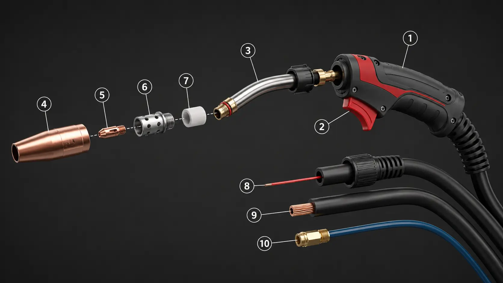
What Parts Make Up the Welding Gun?
The welding gun is where everything comes together. It feeds the wire, delivers the gas, and carries the current right to the joint.

Gun Handle, Trigger, and Gooseneck
The handle is what you hold. The trigger is what makes it all happen. Pull it and the machine sends wire, gas, and current all at once. Let go and everything stops.
Ergonomic handles matter if you weld for hours at a stretch. A cramped grip will wear out your hand fast. If the trigger sticks or the arc stutters when you pull it, the switch inside is wearing out. That is a cheap part to replace, but a dead switch mid-job costs you a whole day.
The gooseneck is the curved metal tube at the front of the gun. It points the contact tip and nozzle toward the workpiece. You will see angles from 30° to 60° depending on the gun model. It gets hot. Run it too hard for too long and the neck distorts or cracks. If the angle starts looking wrong, replace it before the tip misses the joint.
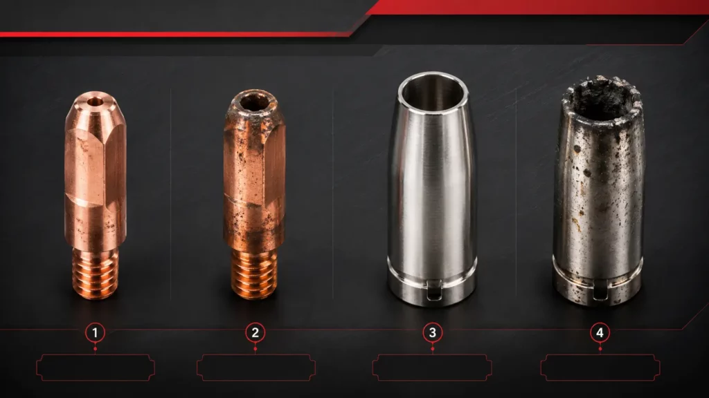
Contact Tip and Gas Nozzle
The contact tip is the last thing the wire touches before it hits the arc. It is a small copper or copper-zirconium piece with a hole bored to match your wire diameter. The bore has to match exactly. Too big and conductivity drops. Too small and the wire jams.
This part wears out fast. Arc blowback elongates the bore. Spatter builds up and chokes the opening. When the arc starts wandering or the wire feeds rough, pop in a new tip. They cost a few cents each, so there is no reason to nurse a worn one. If you run a shop, stock tips in the sizes you use most. Nothing slows down a shift like running out of contact tips.
The nozzle is the brass or copper cap that sits over the contact tip. It shapes the gas flow and shields the weld puddle from the air. You will see conical or cylindrical shapes depending on the gun. Spatter loves to stick to the nozzle bore. When it builds up, gas flow drops and you get porosity. Threads can also strip if you overtighten. Cleaning helps, but once the bore is out of round, replace it.
Gas Diffuser and Insulator
The diffuser sits behind the nozzle and around the contact tip. It has small ports that spread the shielding gas evenly so the puddle stays clean. Without it, gas shoots out in one direction and leaves the rest of the weld exposed. Spatter clogs those ports. Threads strip just like on the nozzle. Check it when you swap the nozzle. If gas flow looks uneven, the diffuser is the first place to look.
The insulator sits between the conductive metal parts of the gun. It keeps current from jumping where it should not go. Without it, you get shorts and arc flare-ups. Heat cracks the insulator over time. If you get random arc-outs or the gun feels hot in the wrong spots, pull the diffuser and check the insulator for cracks or burn marks.
Gun Liner, Power Cable, and Gas Hose
The liner is a flexible steel or polymer tube that runs the full length of the gun cable. It guides the wire from the feeder to the contact tip with as little friction as possible. Kinks are the enemy. A sharp bend at the gun handle or a kink near the feeder end will cause bird-nesting or wire shaving. The liner diameter has to match the wire exactly. Too tight and the wire binds. Too loose and it snakes around inside. When feeding gets rough or you see metal shavings in the gun, replace the liner.
The power cable and gas hose run inside the gun cable bundle. The cable carries welding current. The hose delivers shielding gas from the machine to the gun. Check the insulation for cuts or burn marks. Gas leaks at the fittings show up as bubbles if you spray soapy water on the joints. A damaged cable is a shock hazard, not just a welding problem.
How Does the Wire Feeding System Work?
The wire feeding system pushes electrode wire from the spool to the gun at a steady, controlled speed. If this system hiccups, the arc stutters or dies.
Drive Roll Assembly
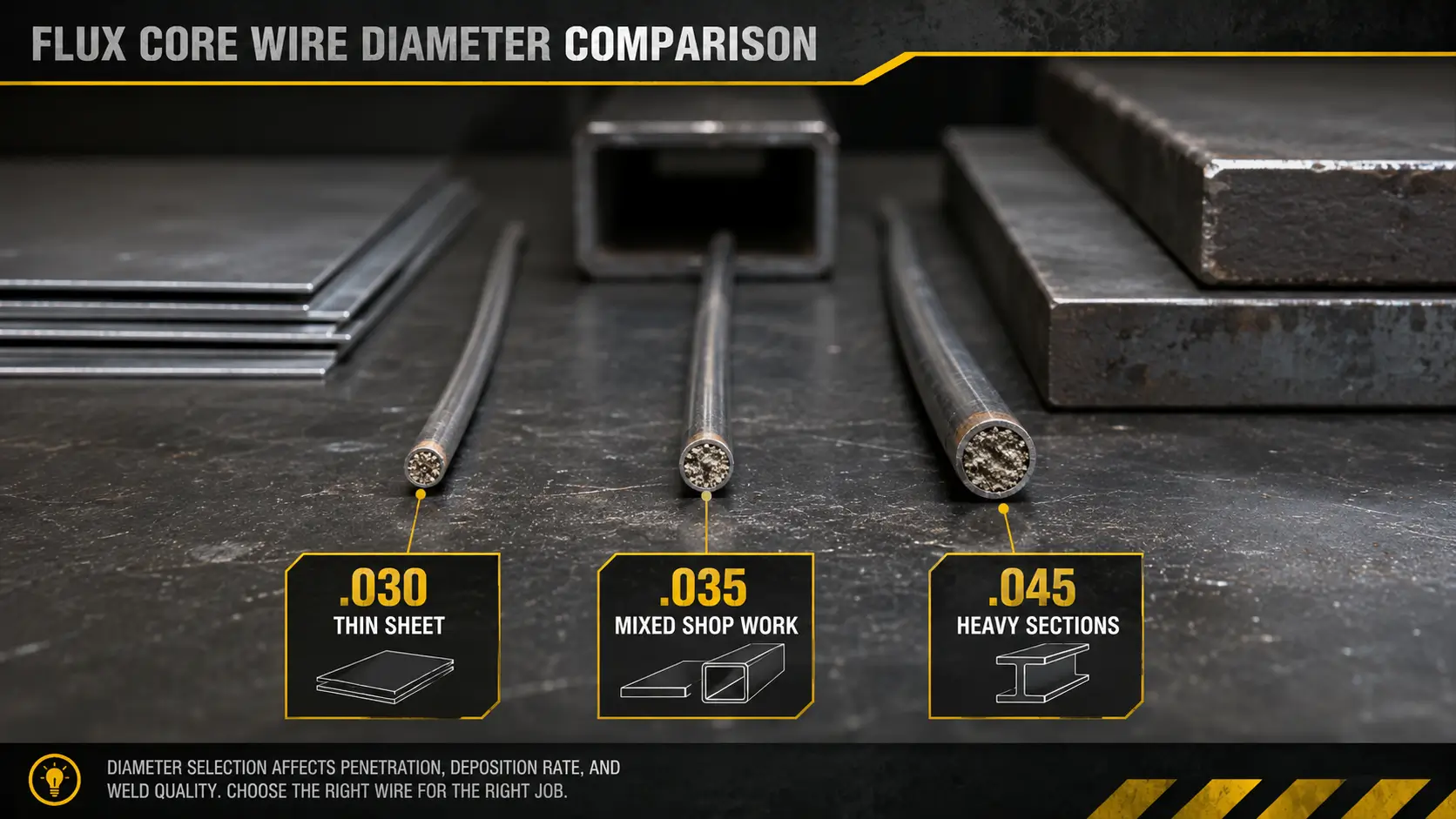
The drive rolls are grooved wheels inside the welder cabinet or wire feeder unit. They grip the wire and push it toward the gun. You have three main types:
- V-knurled rolls bite hard into flux-cored and larger solid wires.
- U-grooved rolls cradle soft wires like aluminum so they do not deform.
- The pressure arm squeezes the wire against the rolls with adjustable tension.
- Too loose and the wire slips. Too tight and you crush or shave the wire.
Worn knurls lose their grip. The wrong groove profile for your wire type causes feeding problems before you even strike an arc. Match the roll to the wire and check tension every time you load a new spool.
Wire Spool Hub and Brake
The spool hub is the spindle that holds your wire supply. It has a friction brake to stop the spool from overrunning when feeding pauses.
If the brake is too loose, the spool keeps spinning and throws wire into a bird-nest behind the drive rolls. If it is too tight, the feeder motor struggles and stalls. Adjust the brake so the spool stops within one revolution when you release the trigger.
Inlet and Outlet Guides
Inlet and outlet guides are small bushings that line up the wire as it enters and leaves the drive rolls. They keep the wire straight so it does not bind or shave.
Misaligned guides chew up the wire and dump metal shavings into the feeder. Check them when you change wire sizes. A guide worn off-center will jam the wire before you finish the first pass.
How Does the Shielding Gas System Work?
The shielding gas system delivers a steady flow of inert or active gas to the weld puddle. Without it, atmospheric contamination ruins the bead.
Gas Inlet Fitting and Solenoid Valve
The gas inlet fitting is the threaded port on the rear or side of the welder. It receives the hose from the regulator. Check the threads when you connect a new cylinder. Damaged threads leak gas and waste money.
Behind the fitting sits the internal solenoid valve. It opens when you pull the trigger and closes after a post-flow delay to protect the hot puddle. If the valve sticks open, gas keeps flowing and empties your cylinder overnight. If it sticks closed, you get porosity because the puddle never sees shielding gas. A slow valve also causes problems. Without enough pre-flow or post-flow, atmospheric air contaminates the weld.
Gas Regulator and Flowmeter
The regulator mounts on the gas cylinder. It drops cylinder pressure from up to 2200 psi down to working pressure, usually 25 to 50 psi. The flowmeter shows your delivery rate in cubic feet per hour (CFH).
Diaphragms wear out. Gauges read wrong. On high-flow jobs, frost can form on the regulator and choke delivery. Check your flow rate at the start of every shift. Do not trust a gauge that has been knocked around.
Gas Cylinder and Valve
The cylinder stores your shielding gas. Pure CO2, argon-CO2 mixes, and tri-mix blends for stainless steel are the most common choices.
Empty cylinders cause obvious problems. Leaky valves are worse because they drain gas slowly while nobody notices. The wrong gas for your material type gives you ugly, weak welds. Label your cylinders clearly and check valves with soapy water when you swap tanks.
What About the Ground Circuit and Safety Components?
Grounding and safety parts sit still and wear slowly, so they are easy to overlook. But the work clamp and ground cable complete the electrical path. Without them the arc wanders or dies. The thermal overload system kills power before the machine cooks itself. These parts protect both weld quality and the machine itself, so they deserve the same attention as your contact tips and nozzles.
Work Clamp and Ground Cable
The work clamp is the heavy-duty spring clamp that bites onto your workpiece or welding table. It completes the circuit so current has a path back to the machine.
Weak spring tension or worn copper plating kills conductivity. If the arc dances around or will not strike, clamp to bare metal and check that the jaws are clean. The ground cable runs from the clamp back to the machine. Look for cuts, burn marks, or loose lugs. A damaged ground cable is a shock hazard, not just a welding problem.
Thermal Overload Protection
Thermal overload protection is a set of internal sensors or breakers that shut the machine down before it cooks itself. It kicks in when you push past the duty cycle or when cooling vents are clogged.
If the machine keeps shutting off mid-weld, you are either running too hot for too long or the cooling system needs cleaning. Do not bypass the breaker. It is there to save the machine from real damage.
How Do You Troubleshoot Common Problems?
When something goes wrong, you do not need to guess. Most symptoms point to one or two specific parts. Here is a quick reference.
| Symptom | First Component to Inspect | Likely Cause |
| Erratic arc / wire burn-back | Contact tip | Worn bore, incorrect size, or loose connection |
| Excessive spatter | Gas nozzle / diffuser | Blockage, poor gas coverage, wrong gas type |
| Wire jamming at gun | Gun liner | Kink, wrong diameter, or excessive debris |
| Intermittent wire feed | Drive rolls | Wrong groove, worn teeth, or incorrect tension |
| Porosity in weld | Gas system | Leaks, low flow, empty cylinder, or solenoid fault |
| Arc starts but no wire feed | Trigger / control board | Switch failure or circuit fault |
Conclusion
Knowing your welder inside and out is not about memorizing part names. It is about cutting downtime and keeping your welds consistent.
Here is what to remember:
- The power source, wire feeder, shielding gas system, welding gun, and ground circuit are the five zones to check when something goes wrong.
- Most feeding and arc problems trace back to the contact tip, liner, drive rolls, or gas nozzle. These are wear items, not permanent fixtures.
- A quick five-minute inspection at the start of each shift prevents hours of rework and scrap.
- Swapping a worn contact tip or clearing a clogged nozzle costs a few dollars. Missing the signs costs you scrap, rework, and lost production time.
- Stocking common consumables at your shop lets your team fix problems on the spot instead of waiting for parts to arrive.
If you are building a welding equipment catalog or stocking a repair shop, your customers need more than machines. They need the consumables that wear out every week.
YesWelder stocks contact tips, liners, drive rolls, gas nozzles, and diffusers for most GMAW systems. We ship in bulk to distribution partners and back you up with bulk pricing, technical guides, and marketing materials your sales team can put to work.
Request a quote or view our catalog to build the parts lineup your customers depend on.
FAQs
GMAW is the technical name for the process. MIG uses inert gas like pure argon. MAG uses active gas like pure CO2 or mixes that contain CO2. Most people say MIG even when they mean MAG.
Contact tips usually last 8 to 24 hours of arc time depending on wire type and amperage. Liners can last several months if kept clean and dry. Inspect the nozzle and diffuser weekly for spatter buildup.
Only if you are using self-shielded flux-cored wire. Solid wire without gas produces porous, weak welds because the molten puddle oxidizes. For regular GMAW, always check that your cylinder has gas and your regulator is set correctly.
Bird-nesting happens when the wire tangles at the drive rolls before entering the gun liner. The most common cause is incorrect drive roll tension or a worn liner that creates too much friction. Check the liner diameter matches your wire size and adjust the pressure arm so the wire feeds smoothly without slipping or crushing.
Burn-back happens when the wire melts too close to the contact tip, usually because the wire feed speed is too low or the voltage is too high for the travel speed. It can also mean your contact tip bore is worn oversized. Check your settings against the machine chart and inspect the tip for elongation or spatter buildup.